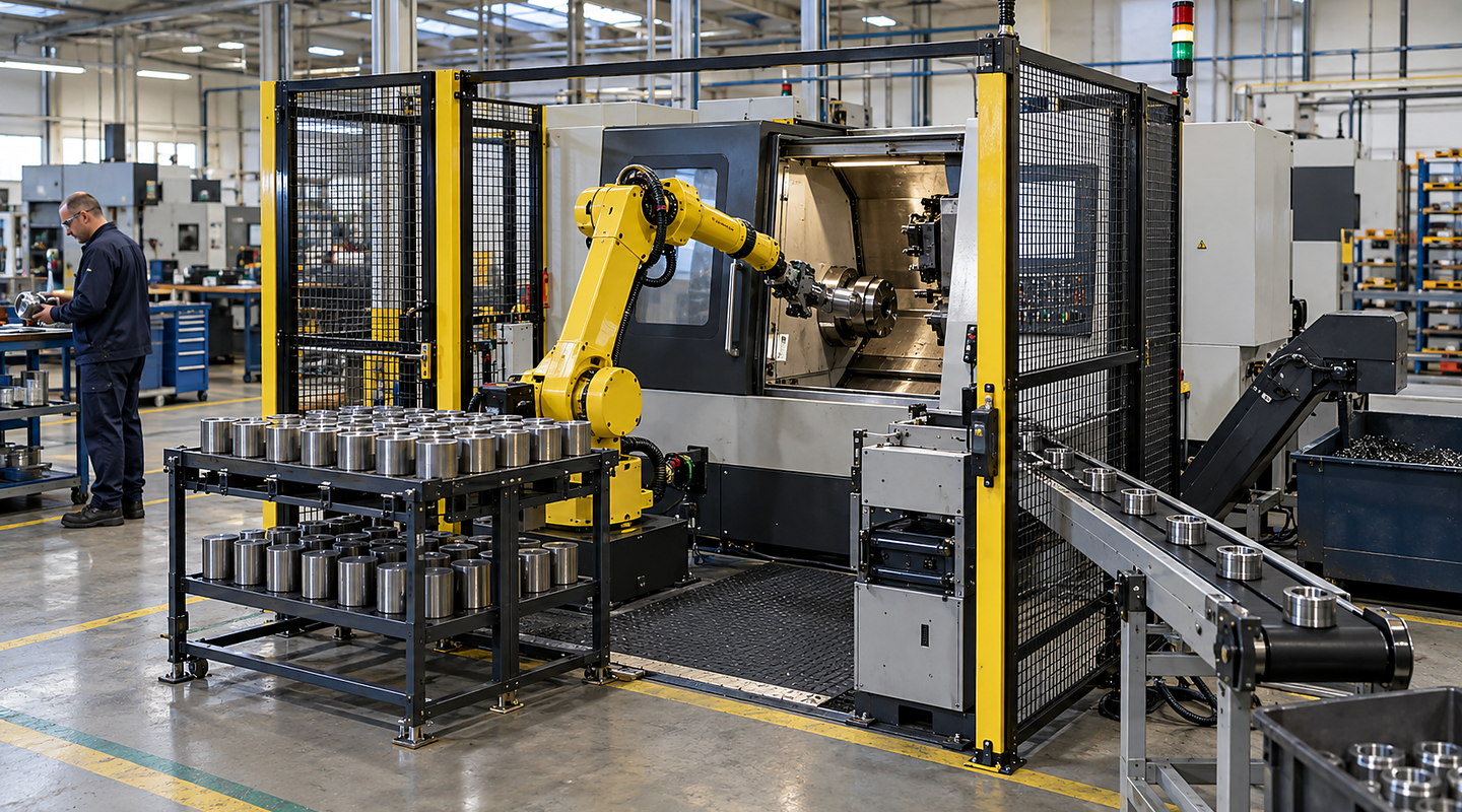
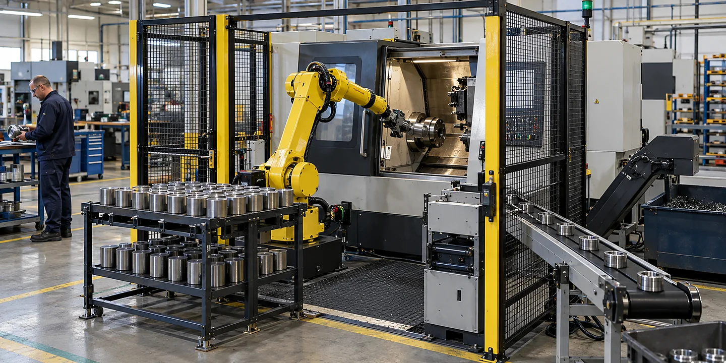
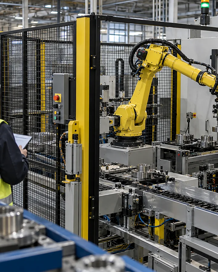
Robotic test automation loads and unloads a defined test process while preserving the link between the component and its result. Specify the fixture, connection sequence, tester interface and release rules together so handling speed does not undermine test validity.
Speak directly with Oxford Industrial Automation about robotic loading of functional tests.
Quick answer
How do we integrate robotic handling with our functional test equipment?
Map part identification, loading, connection, testing and release as one sequence. Define the test equipment’s interfaces and the conditions required for a valid result. Challenge failed tests, interrupted connections and retests, ensuring that each result remains tied to the correct component and its approved next step.
Application decisions
Design the sequence from identified part to recorded result
Decision 1
Define a valid loaded condition
Show how the part locates in the fixture and how seating is confirmed. Include connectors, probes, seals or other interfaces required by the test. The robot reaching a programmed position is not the same as the tester receiving a correctly connected component.
Decision 2
Connect identity to the test request
Define when the part identifier is captured and how the requested test recipe is selected. Keep that identity attached to the fixture position until unloading is complete. Challenge an unreadable identifier or a part moved after the initial scan.
Decision 3
Agree the tester handshake
Document ready, loaded, start, busy, complete, fault and result states as required by the tester. Include timeout and acknowledgement behaviour. The system must distinguish a failed test from a missing or incomplete test result before deciding where the part goes.
Decision 4
Plan cycle time around test duration
Include loading, connection, test execution, disconnection and unloading in the cycle model. If multiple nests are proposed, identify how results remain associated with each position. A faster robot may not improve throughput when the test or connection process determines the cycle.
Decision 5
Control retests and fault recovery
Define who may authorise a retest and whether the first result remains in the record. Include lost connections, interrupted tests and parts left in fixtures. Avoid automatic repeat testing that obscures an intermittent fault or creates an unexplained accepted result.
Decision 6
Release to a defined destination
Specify routes for passed, failed and unresolved parts and the confirmation required at unloading. Retain the test reference, recipe and decision needed for later investigation. Use the robotic test integration guide to allocate tester and cell responsibilities.
Applications
Dedicated test loading or a shared platform?
Compare the part and fixture range, connection work and test duration at each station. A flexible loading concept must preserve test identity and valid connection conditions through every change of product.
Capture fixture loading, connectors, tester states, test duration and result handling.
02
Prove repeatable connections
Trial real part variation and demonstrate the conditions needed for a valid test.
03
Integrate identity and tester control
Agree handshakes, recipe selection, acknowledgements and the result record.
04
Challenge unresolved states
Test timeouts, disconnections, retests and controlled routing of uncertain parts.
Practical decision guide
Compare one test fixture with a multi-nest concept using the full cycle
Start with how long the tester occupies a correctly loaded part, then include connection, handling and result confirmation. A second nest is useful only if the surrounding equipment and control sequence can use the overlap without confusing parts or results.
Calculate the single-fixture reference clearly
In a hypothetical example, 30 seconds of testing plus ten seconds for combined loading, connection and unloading gives a 40-second cycle, or 90 completed cycles per hour before other stops. This is arithmetic for the stated assumptions, not a performance claim. Add any separate settling, discharge or operator work that the real process needs.
Check which tasks may genuinely overlap
Record whether the tester can process more than one nest, whether connections share a resource and when the robot may access each position. Include waiting for a safe access condition and the time needed to confirm a result. Drawing two fixtures does not establish two independent test channels.
Challenge result ownership during a fault
Stop with different states in the two positions: for example one part awaiting a result and another ready to unload. Confirm that a delayed message, timeout or restarted tester cannot be assigned to the wrong part. Keep the nest reference, component identity and test request together until the defined disposition is complete.
Compare useful output and recovery work
Count parts with valid completed results and record unresolved tests, retests and operator interventions separately. Agree retest authority rather than repeating automatically until a pass appears. Use the robotic test integration guide to allocate tester interfaces and the evidence for a production acceptance trial.
Important limits
Know what needs a separate check
Cycle time depends on the complete process rather than robot speed alone.
Part presentation, tolerances and recovery cases must be included in feasibility work.
Collaborative operation or automatic handling cannot be assumed safe without an application assessment.
Your final solution for robotic loading of functional tests must reflect the law, current standards and site-specific risks that apply to your installation.